• Skip to primary navigation
  • Skip to main content
WITT Solutions Logo

WITT Solutions GmbH

SMARTE Messtechnik für Gleichstrom – Spannung – Kabel – Isolation

  • Products
    • DC-Traction power-Monitoring
    • WB measuring platform
      • Extensions for functional modules
    • Isolation-Monitoring
    • Voltage Limiting Device
    • Cable Monitoring
    • Railway Infrastructure
    • Mobile Measuring Systems
    • Stray currents measuring devices
    • Customized Products
  • Services
    • System Engineering
    • Substitution
    • Hardware Development
    • E-planning
    • Testing and system acceptance
    • Maintenance & Repair
    • Manufacture
    • Construction
    • CE conformity
  • Partner
    • International Sales Partner
    • Partner Q&A
  • About Us
    • WITT Solutions GmbH
    • Network
    • Honor
    • Research
    • Project
  • News
  • Career
  • Contact
    • General enquiries
    • Press Inquiry
  • German
  • English
  • Show Search
Hide Search
WB-VDC
WB-VDC - Image 2
WB-VDC - Image 3
WB-VDC - Image 4

WB-VDC

Here you can find out more Sales enquiry

Detects DC voltages and AC components
Dielectric strength up to 6000VDC/10ms

Categories: Monitor and analyse DC. Determine measurement data., WITT-Bridge components Tag: DC driving voltage
  • Description
  • General data
  • Technical specifications
  • Function
  • Extensions
  • Protocol and SCADA
  • Scope of delivery
  • Documents
  • Digital values

Description

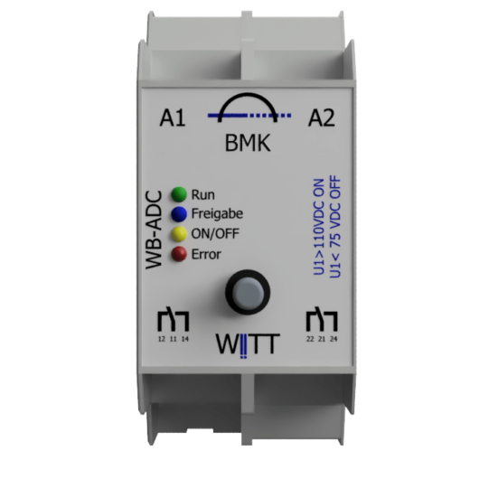
The functional module “WB-VDC” is used wherever power voltages from 200VDC are measured and monitored. In addition, based on the data collected, control decisions can be passed on to third-party systems.

Application examples include:

  • Feed-in points of substations in railway infrastructure
  • Return conductor points from substations in railway infrastructure
  • in the generation of energy and its storage
  • truck charging stations
  • BOAT charging station
  • train charging stations
  • power battery in a BOAT

General data

Supply voltage

24VDC /100mA

Power consumption

5W – 15W

humidity

0 …100%, non-condensing

Outside temperature range

-20 … 50 °C

housing / design

T2 (1 TE = 18 mm) (W x H x D) 36mm x 99mm x 105mm
If option WB-MC T3 (W x H x D) 68mm x 99mm x 105mm
If option measurement display T4 (W x H x D) 90mm x 99mm x 105mm

Modular housing

Protection class IP 20

Mounted on 35 mm DIN rail according to EN 60715

Mains connection and inputs and outputs:

– screw terminals,
– Stripping length 9…10 mm
Note: For connecting potential-free contacts to
the actuator inputs are twisted pair wires
wires to use.
The following conductor cross-sections are permitted:
– solid 0.5 … 2.5 mm2
– finely stranded, with pin cable lug, gas-tight crimped 0.5… 2.5 mm²
– Finely stranded, with ferrule 0.5 … 1.5 mm2
– Finely stranded, untreated 1.0 and 1.5 mm²

weight

approx. 250g

Parameterization

For security reasons and by popular request, there was no on-site configuration option.

The threshold values ​​can be set at the factory.

If you need several different threshold values ​​in your systems, you can do this using the CM1010 / VLD1010 service case. Different parameter sets and software updates can be stored on the service case and imported using an adapter.

It is also possible to transfer the parameters via a SCADA system (the system must be configured using a WB-MC or WB-HS must be connected).

Technical specifications

Standard WB VDC

Analogue input channels (measuring channels)

The nominal voltages are based on the typical power supply of DC railways.

max. Measuring range

+/-345V

+/-860V

+/-1725V

+/-3450V

max. Rated voltage VDC

300

750

1500

3000

Voltage strength VDC

1000 / 10sek

2000 / 10sec

3000 / 10sek

6000 / 10sek

Measurement accuracy

see measurement channel variants

We provide two variants of measurement channels:

Product type

withe line

silver line

Measuring channels

2

Sampling rate

up to 15kHz

up to 25kHz

Resolution

up to 8 bits

up to 16 bit

Measurement accuracy

5% of max. value

0.5% of max. value

Output channels digital

number

2

Technology

Relay with 2 separate changeover contacts (NC/ NO)

switching voltage

max. 250V

switching current

max. 8A

switching capacity

max. 2000VA / 60W

Dielectric strength coil – contact

max. 4kVAC

Switching cycles at Imax

> 1,000,000

electrical strength contact-contact

max. 2000VAC

Show

Possible variants depending on the range of functions or options

LED1

green

Run

operability permanently ON

LED2

blue

Enable

Approval granted by higher authority

LED3

green

ON/ OFF

Sonicated On / OFF

LED4

red

Error

Functional malfunction of the system or sensors or equipment

Operation

No controls are provided in the standard system.

Function

The following measurement functions can be carried out, evaluated and displayed using the digital outputs or, if available, transmitted via a protocol

  • Detects high and low voltage

  • DC voltage measurement

  • AC voltage measurement

  • Measurement of mixed voltage

  • Storage of maximum DC voltage value (since last reset)

  • Save max voltage value AC (since last reset)

Voltage up to +/- 3000 V can be reached through a direct connection to the system can be determined directly on the device.

Extensions

Functional extension

Max. DC voltage threshold

Display threshold exceeded

Max. AC voltage threshold

Display threshold exceeded

Min. DC voltage threshold

Displayed below threshold

times event pending

Time(s) for how long a threshold must be present in order to be displayed

Monitored auxiliary voltage for external sensors

The sensors are connected to the device and supplied via it. The power consumption is monitored and conclusions are drawn about the functionality of the sensor.

Number and time of voltage overshoot and undershoot

Example Only if an impulse of > 0.2 ms has occurred, this is counted and after 4 times a signal is sent

Any signal delay

higher-level systems only signal messages when an ACTUAL value is below or exceeded

Any signal pause / min. signal length

Ensuring transmission to third-party systems

Service

The following functions can be offered as an option. These may also require WBex components

Test button

This optional button can be used to manually activate messages or applications 1)

Reset measured value

Using this option, max. or min. measured value storage can be rested 1)

Release contact

The release signal is required if the WB component works autonomously and should be activated or deactivated by a simple signal.

LCD display

ACTUAL value DC

ACTUAL value AC
Max value DC (since last reset)
Max value AC (since last reset)

1)at least one channel of the digital Inputs Extension required


Optional extension

Self-test function

With this extension, the two redundant measurement inputs can check themselves and detect errors.

Input signals

The functionality of the basic components can be extended by an internal extension OR by another WB component or “WBex” extension.

Product

Application examples

WB extensions 4 digital inputs

Release contact 24VDC,
Reset button

Output signals

The functionality of the basic components can be extended by an internal extension OR by an additional WB component.

Product

Examples of use

WB extensions 2 digital power outputs

Switching an actuator or signaling contacts, e.g. 220VAC

WB extensions 4 digital outputs

SMART OK / NOK Status

WB component 2 digital power outputs

Simple on-site extension of the component

Protocol and SCADA

Product

Examples of use

WB – multi-communication

WB component by means of which the WB component is connected to e.g. SCADA

WB – Headstation

WB component with which the WB component can implement any complex task. E.g. measurement data evaluation or graphic displays

Scope of delivery

  • Instruction manual

  • Installation Instructions

  • Unit of measurement

  • Packaging

Documents

Data sheets

No documents currently available

Data sheet

Currently no documents available

Fiches techniques
Aucun document available for the moment

Digital values

The following digital values ​​can be passed on by the components to third-party systems or queried by third parties.
Possibilities are also listed depending on the components, configuration, installed options and system structure as well as the protocol used.

values- output

  1. Product type including extension
  2. Serial number including the extension
  3. Article number
  4. Soft and hardware versions
  5. ACTUAL VDC voltage at the time of request per channel
  6. ACTUAL VAC voltage at time of request per channel
  7. Date + max peak VDC value since last reset
  8. Date + max peak VAC value since last reset
  9. Date + last binary signaling e.g. threshold exceeded
  10. Number of switching operations per output channel since commissioning

values ​​input

    1. threshold values ​​/ target values ​​for switching digital outputs
    2. Threshold values ​​/ target values ​​for escalation via protocol
    3. Software Update
    4. Additional parameters for configuring stored individual programs

Operational Status

  1. Error with error code
  2. Run
  3. Standby
  4. Automatic

Command

  1. Perform self-test
  2. Reset System
  3. Reset switch counter
  4. Reset measurement tips
  5. Switch to standby mode
  6. Switch to automatic mode

Related products

  • WITT TVM 3 | FSM100 driving voltage monitoring

    WITT TVM 3 | FSM100 Driving voltage monitoring

    monitors direct current – contact line voltages up to 750 VDC – fixed threshold values – no auxiliary voltage

    Here you can find out more Sales enquiry
  • WITT WB-CM 3 Cabel monitoring

    WITT WB-CM 3 Cabel monitoring

    Detection and reporting of imperfections in cables

    Here you can find out more Sales enquiry
  • WB-ADC

    WB-ADC

    Determines direct currents and their flow directions.

    • Dielectric strength continuously 3000 VDC
    • high security standard
    Here you can find out more Sales enquiry

Footer

WITT Solutions GmbH

Dyrotzer Ring 3

14641 Wustermark near Berlin
Germany

Phone +49 33234 243 30
Fax +49 33234 243 302
 

© 2025 witt-solutions.de · WITT Solutions GmbH · Wustermark / Germany · GF Klaus Gradischek

Keep In Touch

  • Facebook
  • Instagram
  • LinkedIn
  • Twitter
  • YouTube
  • Contact
  • Privacy policy
  • Impressum
  • Career
  • General terms and conditions
  • Deutsch