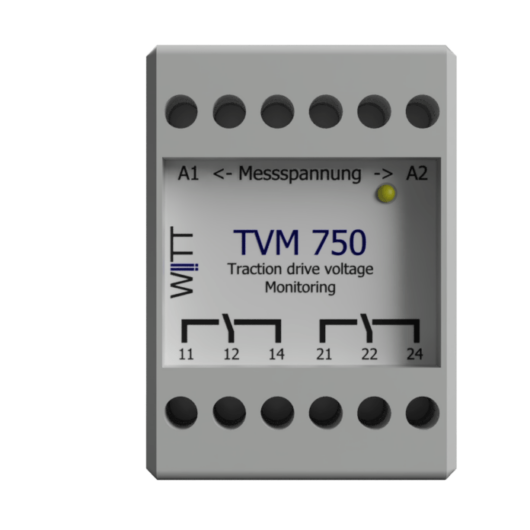
• Skip to primary navigation
  • Skip to main content
  • Skip to primary sidebar
WITT Solutions Logo

WITT Solutions GmbH

SMARTE Messtechnik für Gleichstrom – Spannung – Kabel – Isolation

  • Products
    • DC-Traction power-Monitoring
    • WB measuring platform
      • Extensions for functional modules
    • Isolation-Monitoring
    • Voltage Limiting Device
    • Cable Monitoring
    • Railway Infrastructure
    • Mobile Measuring Systems
    • Stray currents measuring devices
    • Customized Products
  • Services
    • System Engineering
    • Substitution
    • Hardware Development
    • E-planning
    • Testing and system acceptance
    • Maintenance & Repair
    • Manufacture
    • Construction
    • CE conformity
  • Partner
    • International Sales Partner
    • Partner Q&A
  • About Us
    • WITT Solutions GmbH
    • Network
    • Honor
    • Research
    • Project
  • News
  • Career
  • Contact
    • General enquiries
    • Press Inquiry
  • German
  • English
  • Show Search
Hide Search
WB-TVM - Vorderansicht
WB-TVM - Seitenansicht

WB-TVM

Here you can find out more Sales enquiry

Using robust analog and digital measurement technology, the driving voltages of DC railways are measured and directly evaluated.

  • no auxiliary voltage up to 1000 VDC
  • Input voltage up to 2000 VDC/10sek
  • High flexibility in evaluation
  • Settings are made at the factory
Categories: Monitor and analyse DC. Determine measurement data., WITT-Bridge components, WITT-Bridge measuring platform Tags: DC driving voltage, Funktionales Modul, Gleichspannungsüberwachung, Spannungsrelais, Spannungswächter
  • Description
  • Function
  • General data
  • Technical Data
  • Extensions
  • Scope of delivery
  • Protocols and SCADA
  • Documents
  • Digital values

Description

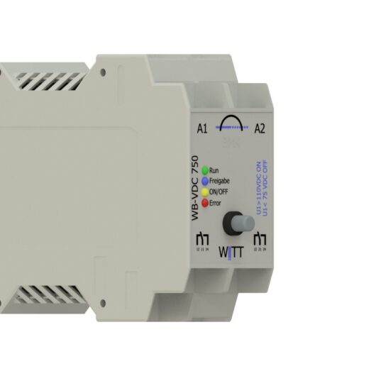
The WB-TVM is typically as a voltage monitor for contact line voltage DC traction systems and for data acquisition to ssensitive point of the infrastructure used.

This is necessary, for example, if measurements have to be carried out before connecting the different parts of the S-Bahn or U-Bahn.

An electrical connection of the sections may only be made if all voltage values ​​are within a certain window.

Another area of ​​application is the display of high voltages in safety areas, e.g. a power rail in the subway area.

Function

The WB TVM

  • can be used as an independent component or in combination with other WB components,

  • enables a reliable evaluation of the driving voltage t,

    due to a special evaluation

  • requires no supply voltage up to 1000 V,

  • offers high flexibility in evaluation,

  • can store peak values ​​locally and

  • automatically activates the measurement.

The WB-TVM evaluates the measurement voltage when the minimum measurement voltage VDC is applied.

The specific firmware enables the WB-TVM to filter the driving voltage so that an exact evaluation is possible.

Depending on the stored threshold values ​​or optional functions, the measured values ​​are evaluated and the outputs are sounded.

In combination with the components WB-BUS, WB-HS, the WB-TVM can also exchange the circuits, the ACTUAL values ​​and target values ​​with a SCADA system.

General data

Supply voltage

  • 1000 V no supply voltage

  • in combination with other WB components via internal BUS

humidity

30%-70% non-condensing

Outside temperature range

-20 up to 50 °C

housing / design

T2 (1 TE = 18 mm) (W x H x D) 36mm x 99mm x 105mm
With option “WB-MC T3” (W x H x D) 68mm x 99mm x 105mm
With Ooption “Measurement display T4” (W x H x D) 90mm x 99mm x 105mm

Modular housing

Protection class IP 20

Mounted on 35 mm DIN rail according to EN 60715

Mains connection and inputs and outputs:

– screw terminals,
– Stripping length 9to 10 mm
Note: For connecting dry contacts to
the actuator inputs are twisted pair wires
wires to use.
The following conductor cross-sections are permitted:
– solid: 0.5 to 2.5 mm2
– Finely stranded, with pin cable lug, gas-tight crimped: 0.5to 2.5 mm²
– Finely stranded, with ferrule: 0.5 to 1.5 mm2
– Finely stranded, untreated: 1.0 and 1.5 mm²

Technical Data

Operation without auxiliary voltage

Min. Measuring Voltage VD

Rating VDC

Voltage proof VDC

10

110

1000

80

400

1000

220

750

1800

220

1500

2000

220

3000

6000

Standard WB VDC

Input channels analog

The nominal voltages are based on der tTypical energy supply of direct current railways.

Without auxiliary voltage
Measuring range

40- 300VDC

200 – 750VDC

200- 1500VDC

200 – 3000VDC

With auxiliary voltage
Measuring range

0 – 345VDC

0-860VDC

0-1725VDC

0-3450VDC

max. Rated voltage VDC

300

750

1500

3000

Voltage strength VDC

750 / 10sek

2000 / 10sec

3600 / 10sec

6600 / 10sek

VDC test voltages

1.5 kV

6 kV

9 kV

12 kV

Measurement accuracy

see measurement channel variants

We provide two variants of measurement channels

Product type

withe line

silver line

Measuring channels

2

Sampling Rate

up to 15kHz

up to 25kHz

Resolution

up to 8 bits

up to 16 bit

Measurement accuracy

5% of max. value

0.5% of max. value

Output channels Digital

number

2

Technology

Relay with 2 separate changers (NC/NO)

switching voltage

max. 250V

switching current

max. 8A

switching capacity

max. 2000WAC / 60W

Dielectric strength coil – contact

max. 4kVAC

Switching cycles at Imax

> 1,000,000

Disconnect Voltage

2000 VAAC / 60 VADC

Show

Possible variants depending on the range of functions or options

LED

LED Color

Caption

Function

1

green

run

operability permanently ON

2

blue

Enable

Approval granted by higher authority

3

green

ON/ OFF

Sonicated On / OFF

4

red

Error

Functional malfunction of the system or sensors or equipment

Operation

Im standardssystem is no control element vintended.

Extensions

Functional extension

Max. DC voltage threshold

Display threshold exceeded

Max. AC voltage threshold

Display threshold exceeded

Min. DC voltage threshold

Displayed below threshold

times event pending

Time(s) for how long a threshold must be present in order to be displayed

Monitored auxiliary voltage for external sensors

The sensors are connected to the device and supplied via it. The power consumption is monitored and conclusions are drawn about the functionality of the sensor.

Number and time of voltage overshoot and undershoot

Example: Only if an impulse of > 0.2 ms has occurred, this is counted and after 4 times a signal is sent

Any signal delay

higher-level systems only signal messages when an ACTUAL value is below or exceeded

Any signal pause / min. signal length

Ensuring transmission to third-party systems

Secure blocking of external switching commands

To ensure unintentional switching, e.g. Canat the firmware level, the bidirectional communication can not only be deactivated but blocked by the compilation,

Service

The following functions can be offered as an option. These may also require WBex components

Test button

This optional button can be used to manually activate messages or applications 1)

Reset measured value

Using this option, max. or min. measured values ​​can be saved 1)

Release contact

The release signal is required if the WB component works autonomously and is to be activated or deactivated by a simple signal

LCD display

ACTUAL value DC

ACTUAL value AC
Max value DC (since last reset)
Max value AC (since last reset)

Parameterization

For security reasons, there was no on-site configuration option.

The thresholds can be set at the factory.

If you need several udifferent threshold values ​​in your systems, you can use our service case CM1010 / VLD1010 . With the servicekoffer, different parameter sets as well as Softwareupdates are stored and imported by an adapter.

Parameterization via SCADA Systems is possible if the system is connected to a WB-MC or WB-HS .

Input signals

The functionality of the basic components can be extended by an internal extension OR by another WB component or WBex extension become.

Product

Application examples

WB extensions 4 digital inputs

Release contact 24VDC,
Reset button

Output signals

The functionality of the basic components can be extended by an internal extension OR by another WB component.

Product

Application examples

WB extensions 2 digital power outputs

Switching an actuator or signaling contacts, e.g. 220VAC

WB extensions 4 digital outputs

SMART OK / NOK Status

WB Component 2 Digital Power Outputs

Simple on-site extension of the component

1)at least one channel of the digital Input extension needed

Scope of delivery

The following items are included in the scope of delivery:

  • Instruction manual
  • Installation instructions
  • Unit of measurement
  • Packaging
  • Test report

Protocols and SCADA

Product

Application examples

WB – Multi-Communication

WB component by means of which the WB component can be connected to e.g. SCADA

WB – Headstation

Any complex tasks can be implemented using these components. e.g. measurement data evaluation, graphic displays

Documents

Datenblätter

Derzeit keine Dokumente vorhanden

Datasheet

Currently no documents available

Fiches techniques
Aucun document disponible pour le moment

Digital values

The following digital values ​​can be passed on by the components to third-party systems or queried by third parties.
Possibilities are also listed depending on the components, configuration, installed options and system structure as well as the protocol used.

values- output

  1. Product type including extension
  2. Serial number including the extension
  3. Article number
  4. Soft and hardware versions
  5. ACTUAL voltage at the time of request per channel
  6. Date + max peak value since last reset
  7. Date + last binary signaling e.g. threshold exceeded
  8. Number of switching operations per output channel since commissioning

values ​​input

  1. Threshold values ​​/ target values ​​for switching digital outputs
  2. Threshold values ​​/ target values ​​for escalation via protocol
  3. Software Update

operational status

  1. Error with error code
  2. Run
  3. Standby
  4. Automatic

Command

  1. Perform self-test
  2. Reset System
  3. Reset switch counter
  4. Reset measurement tips
  5. Switch to standby mode
  6. Switch to automatic mode

You may also like…

  • WBex DI4

    WBex DI4

    Extension of a WB component by up to four digital inputs

    Here you can find out more Sales enquiry
  • WBex DO2

    WBex DO2

    Extension of a WB component by up to two potential-free changeover contacts

    Here you can find out more Sales enquiry
  • WBex DO4

    WBex DO4

    Extension of a WB component by up to four potential-free changeover contacts

    Here you can find out more Sales enquiry

Related products

  • WITT WB-CM 3 Cabel monitoring

    WITT WB-CM 3 Cabel monitoring

    Detection and reporting of imperfections in cables

    Here you can find out more Sales enquiry
  • WITT TVM 3 | FSM100 driving voltage monitoring

    WITT TVM 3 | FSM100 Driving voltage monitoring

    monitors direct current – contact line voltages up to 750 VDC – fixed threshold values – no auxiliary voltage

    Here you can find out more Sales enquiry
  • WB-VDC

    WB-VDC

    Detects DC voltages and AC components
    Dielectric strength up to 6000VDC/10ms

    Here you can find out more Sales enquiry

Primary Sidebar

Newsletter

Sign up to receive email updates and to hear about our latest adventures!

We won't sell your email or send you spam.

Search our site

Footer

WITT Solutions GmbH

Dyrotzer Ring 3

14641 Wustermark near Berlin
Germany

Phone +49 33234 243 30
Fax +49 33234 243 302
 

© 2025 witt-solutions.de · WITT Solutions GmbH · Wustermark / Germany · GF Klaus Gradischek

Keep In Touch

  • Facebook
  • Instagram
  • LinkedIn
  • Twitter
  • YouTube
  • Contact
  • Privacy policy
  • Impressum
  • Career
  • General terms and conditions
  • Deutsch