• Skip to primary navigation
  • Skip to main content
WITT Solutions Logo

WITT Solutions GmbH

SMARTE Messtechnik für Gleichstrom – Spannung – Kabel – Isolation

  • Products
    • DC-Traction power-Monitoring
    • WB measuring platform
      • Extensions for functional modules
    • Isolation-Monitoring
    • Voltage Limiting Device
    • Cable Monitoring
    • Railway Infrastructure
    • Mobile Measuring Systems
    • Stray currents measuring devices
    • Customized Products
  • Services
    • System Engineering
    • Substitution
    • Hardware Development
    • E-planning
    • Testing and system acceptance
    • Maintenance & Repair
    • Manufacture
    • Construction
    • CE conformity
  • Partner
    • International Sales Partner
    • Partner Q&A
  • About Us
    • WITT Solutions GmbH
    • Network
    • Honor
    • Research
    • Project
  • News
  • Career
  • Contact
    • General enquiries
    • Press Inquiry
  • German
  • English
  • Show Search
Hide Search
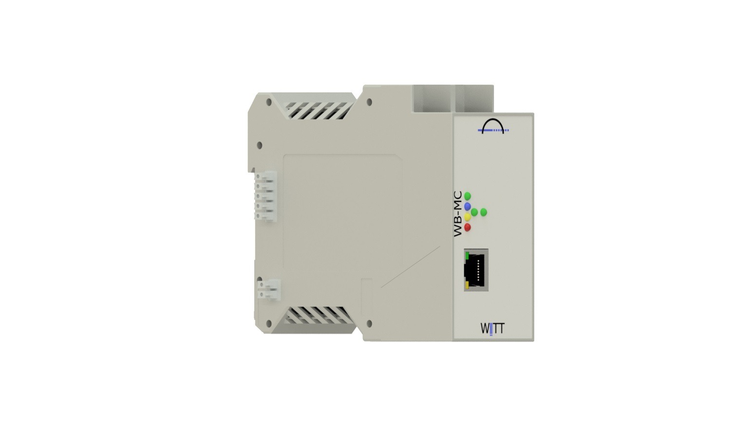
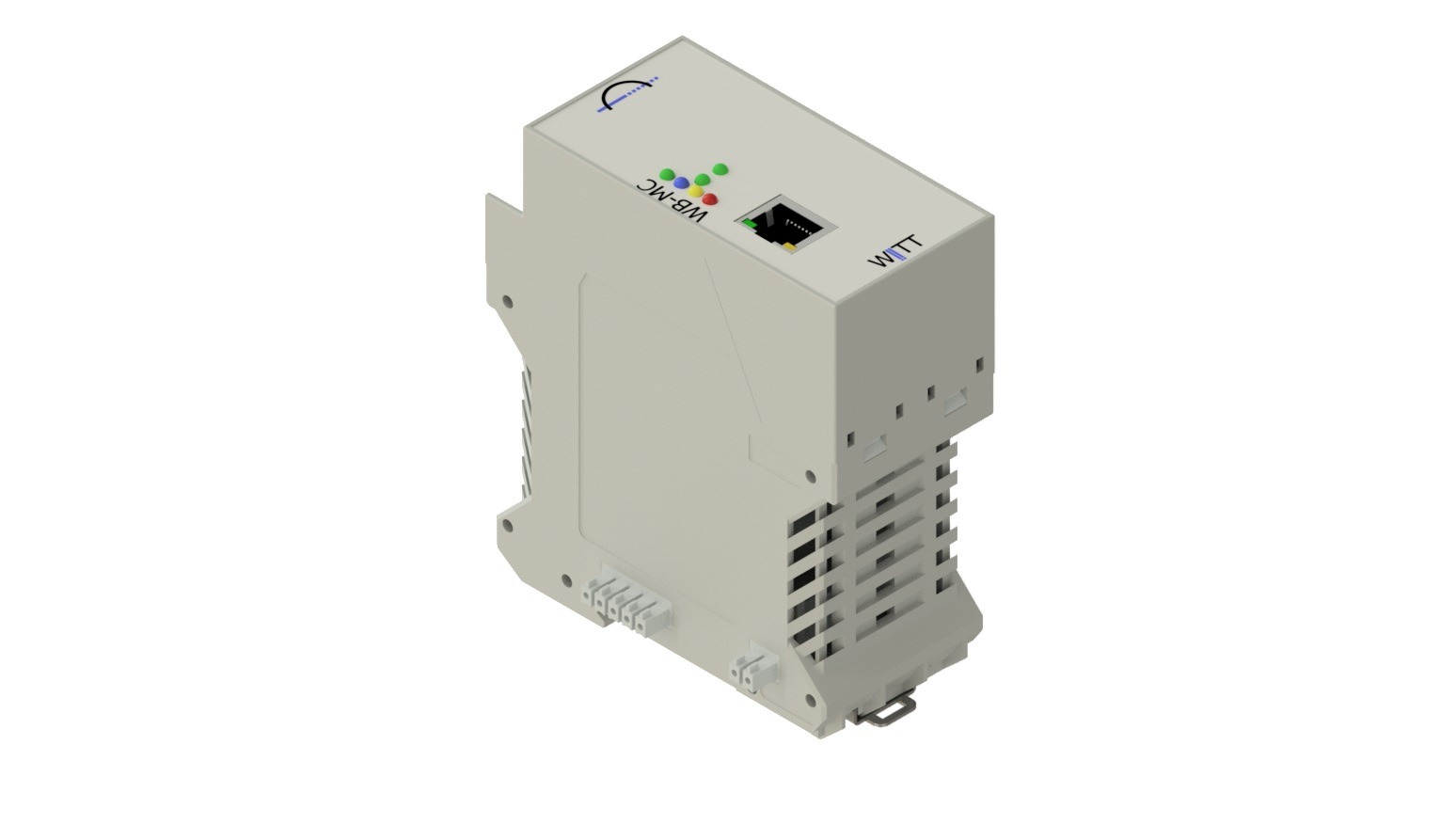
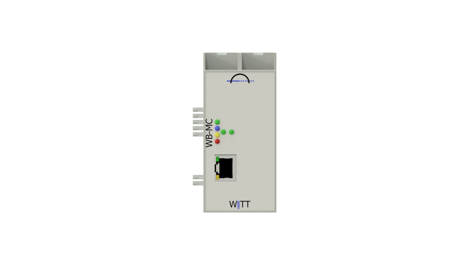
WB-MC
WB-MC - Image 2
WB-MC - Image 3

WB-MC

Here you can find out more Sales enquiry

Communicative networking of WB components

Category: Extension for functional modul Tag: Communication
  • Description
  • Function
  • Technical specifications
  • General data
  • Scope of delivery
  • Digital Values

Description

The WB component “WB-MC” enables communicative networking with remote components among themselves. It also supports the exchange of information with third-party systems via standard protocols.

There are two typical areas of application:

1.) Communicative connection of a WITT Bridge measurement extension to a higher-level SCADA system.

2.) Connection of different WB components to monitor the cable infrastructure. Optionally, a WB-HS can monitor and configure everything centrally.

Product WB-MC Variant:

CANopen 1 channel 12mm
CANopen 2 channel 12mm
IEC 60870-5-103 / DIN EN 60870-5-103
IEC 60870-5-104 / DIN EN 60870-5-104
IEC 61850
ModBus/TCP
ModBus/RTU
PROFIBUS
other variants on request

Function

The WB-MC component is connected to the WB backplane bus with third WB components. The WB component “translates” information from the WB components connected to the backplane bus and the external protocol.

Depending on the protocol used and the WB components, a wide variety of quantities and information can be transmitted:

  • operational status
  • control commands
  • real value
  • target values
  • event-based transmission
  • no “real-time” transmissions

Technical specifications

Product WB-MC variant:

  • CANOpen 1 channel 12mm

  • CANOpen 2 channel 12mm

  • IEC 60870-5-103 / DIN EN 60870-5-103

  • IEC 60870-5-104 / DIN EN 60870-5-104

  • IEC 61850

  • ModBus/TCP

  • ModBus/RTU

  • PROFIBUS

  • other variants on request

each with galvanic isolation

  • up to 4 kV

  • up to 1.5 kV

  • gdepends on the communication variant

Analog input channels (measuring channels)

NONE

Digital input channels

NONE

Output channels digital

NONE

Display

Possible variants depending on the range of functions or options

LED

color

Caption

Description

1

green

Run

Permanently ON: Operational

2

green

Run

Duration ON:

Flashes: Component boots and connects to the backplane BUS and external units

3

red

Error

Functional malfunction of the system or sensors or equipment

Parameterization

“Configuration profiles” are stored in the servicekoffer CM1010 / VLD1010 and transferred to the WB component.

General data

Supply voltage

Via backplane BUS

Power consumption

humidity

0 up to 100%, non-condensing

Outside temperature range

-20 up to 50 °C

Housing

Protection class IP 20

DIN rail housing. Mounting on 35 mm DIN rail according to EN 60715

Mounted housing

Dimensions: T2 (W 36 x H x D) mm

Mains connection and inputs and outputs:

Depending on the protocol used

RJ45

12 mm round connector

LWL connections

weight

400g

Scope of delivery

  • operation manual
  • installation Guide
  • WB component / circuit board
  • packaging
  • test protocol

Digital Values

The following digital values ​​can be passed on by the components to third-party systems or queried by third parties.
Possibilities are also listed depending on the components, configuration, installed options and system structure as well as the protocol used.

values- output

  1. Product type including extension
  2. Serial number including the extension
  3. Article number
  4. Soft and hardware versions
  5. Type protocol and its configuration

values ​​input

  1. Parameters for configuring the installed protocol

operational status

  1. Error with error code
  2. Run
  3. Standby
  4. Automatic

Command

  1. Perform self-test
  2. Reset System
  3. Reset switch counter
  4. Switch to standby mode
  5. Switch to automatic mode

Related products

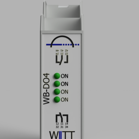
  • WB-DO

    WB-DO

    WITT Bridge Digital Outputs

    High separation voltage of up to 2000 VDC / 20ms

    Here you can find out more Sales enquiry
  • WBex DI4

    WBex DI4

    Extension of a WB component by up to four digital inputs

    Here you can find out more Sales enquiry
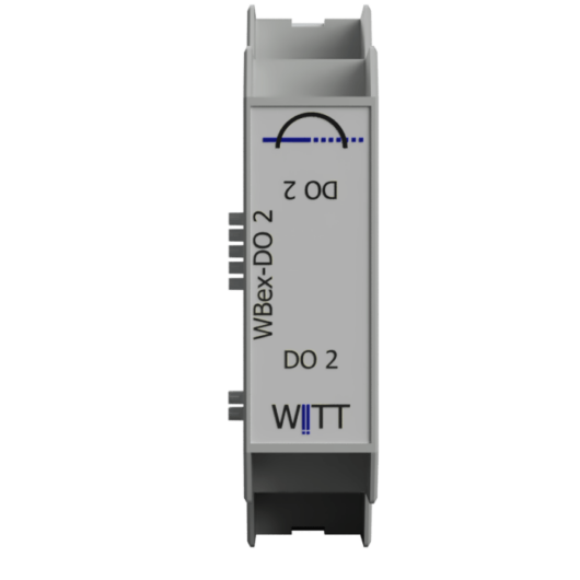
  • WBex DO2

    WBex DO2

    Extension of a WB component by up to two potential-free changeover contacts

    Here you can find out more Sales enquiry

Footer

WITT Solutions GmbH

Dyrotzer Ring 3

14641 Wustermark near Berlin
Germany

Phone +49 33234 243 30
Fax +49 33234 243 302
 

© 2025 witt-solutions.de · WITT Solutions GmbH · Wustermark / Germany · GF Klaus Gradischek

Keep In Touch

  • Facebook
  • Instagram
  • LinkedIn
  • Twitter
  • YouTube
  • Contact
  • Privacy policy
  • Impressum
  • Career
  • General terms and conditions
  • Deutsch